

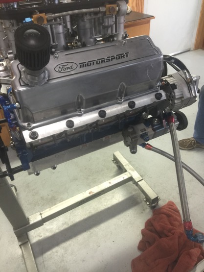
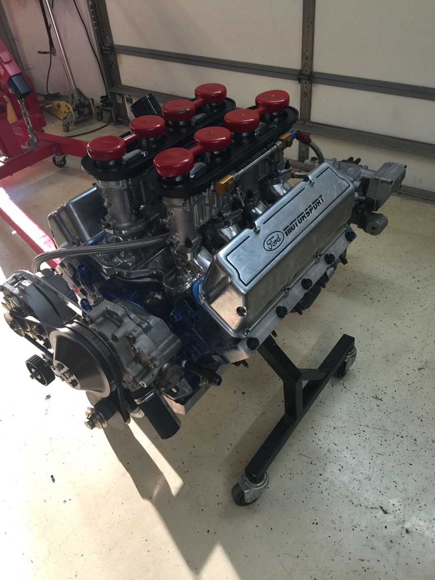
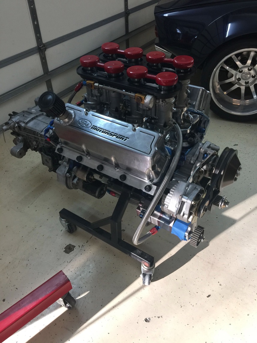
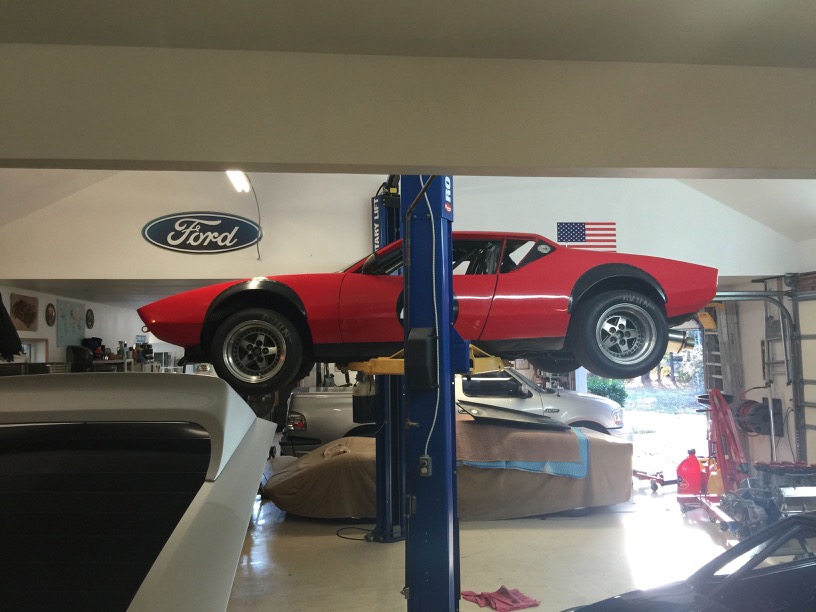
The new engine… with super support from Upton's Speed Shop
A new all iron engine for the race car.
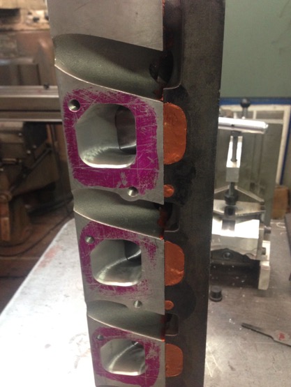
Iron 4V Cleveland heads with exhaust port plates.
Iron SVO siamese block with 302 main bearings.
Along the lines of The Trials of Thomas Covenant, The Unbeliever, here's the build story as it unfolds.
Tom went through an apprenticeship with Joe Halliday and I'm kinda' doing the same.
Learning a lot. Getting chastised a lot…
Tom says I'm lucky though… He hasn't thrown any wrenches at me yet!
I did get a lacquer thinner soaked rag in my face though…
Ashley has helped, too!
Here are pictures, videos and the saga.
Some taken at USA Racing, most taken at Tom's shop and then my garage once the engine was finished.
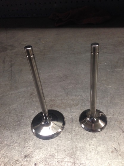
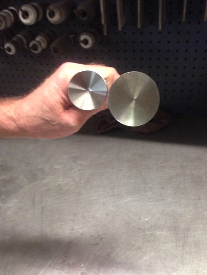
The valves…. Titanium and nickel chromate coated.
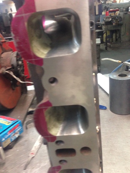
Head work in progress. Valve guides and port plates installed. Porting intake side.
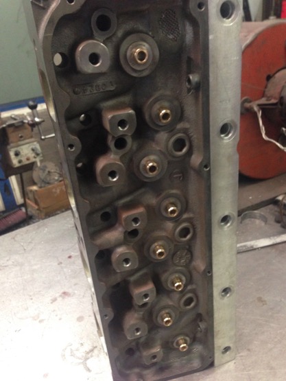
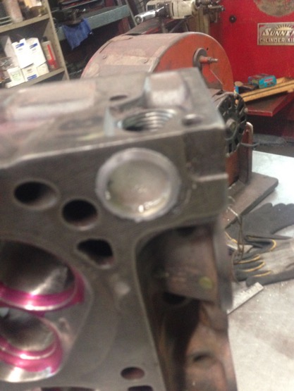
Combustion chamber and exhaust work in progress.
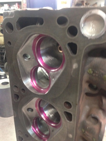
Gotta’ plug the water holes in the Cleveland heads to work on the Windsor style block.
The heads were also ‘pinned’ as per the good old ’70’s when guys like Bob Glidden used to run high compression.
The heads would flex and blow head gaskets. Some bolts in strategic places and they will handle 14:1 compression.
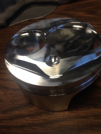
A CP piston, top view and bottom view. Ain’t they purty…
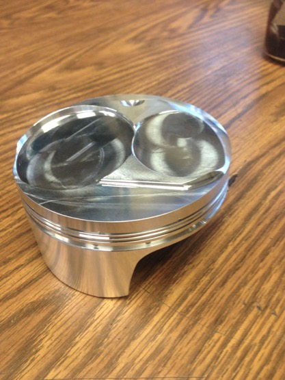
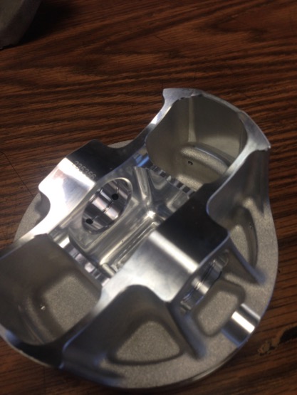
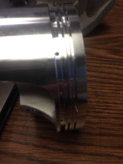
A piston side view and the other side of the top.
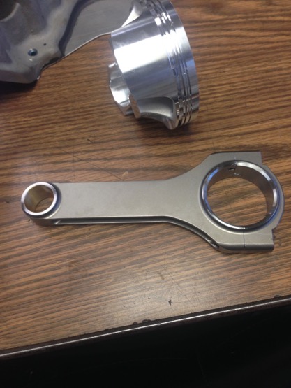
With a Dyer rod.
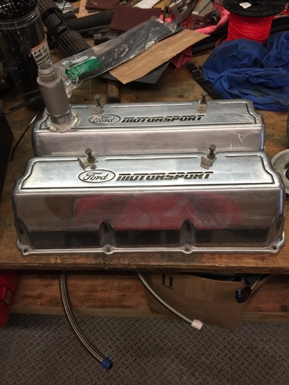
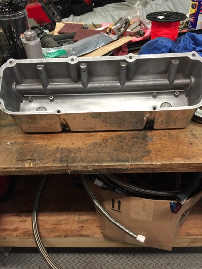
Pics of some other goodies… Front cover and valve covers with oil squirters for the valve springs.
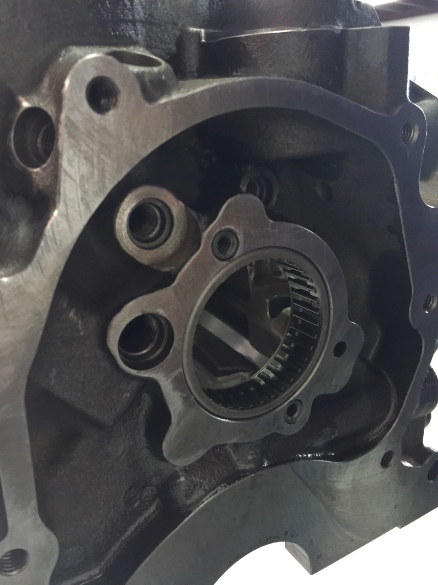
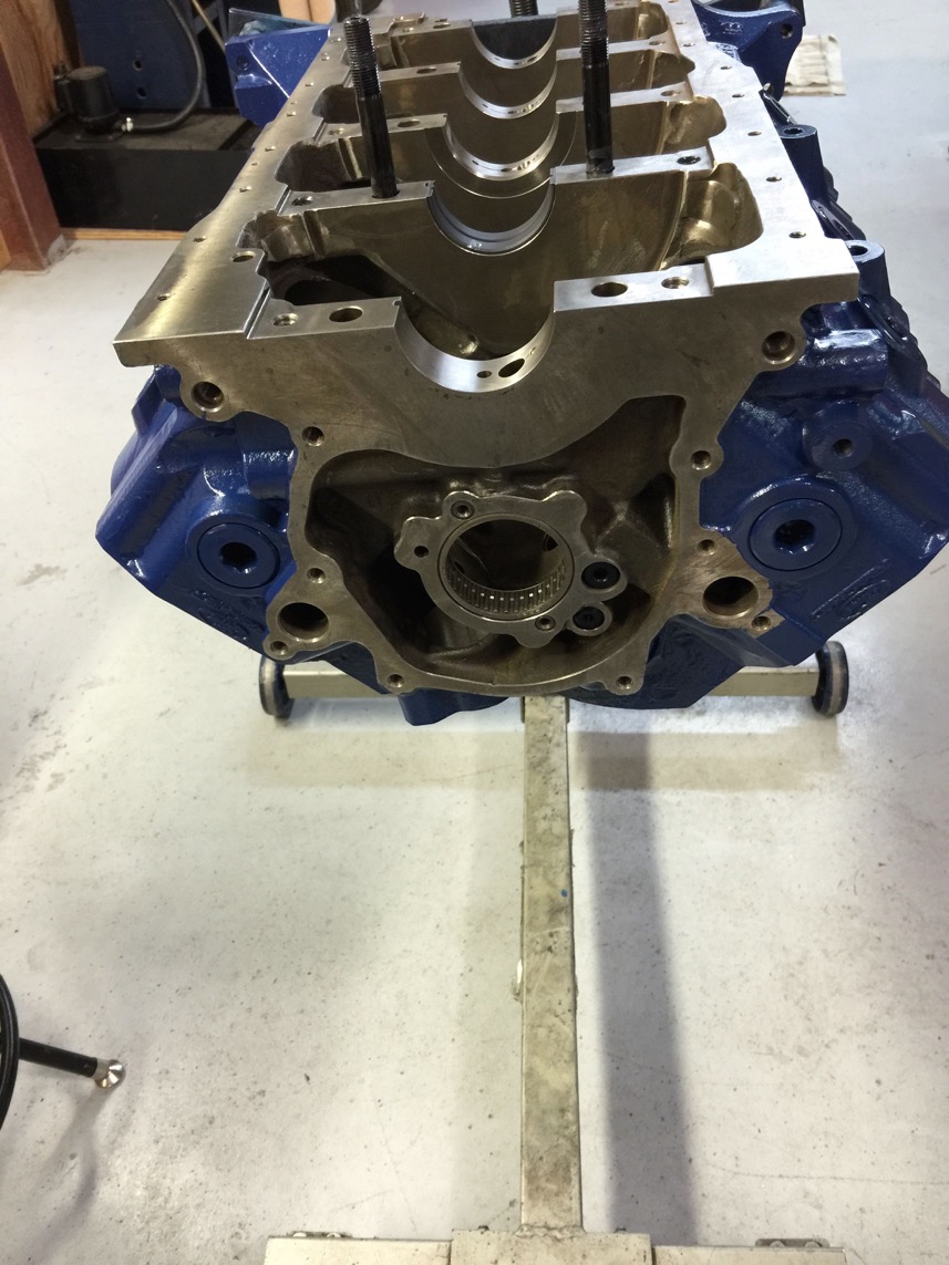
The block after needle cam bearings and freeze and oil plugs have been installed.
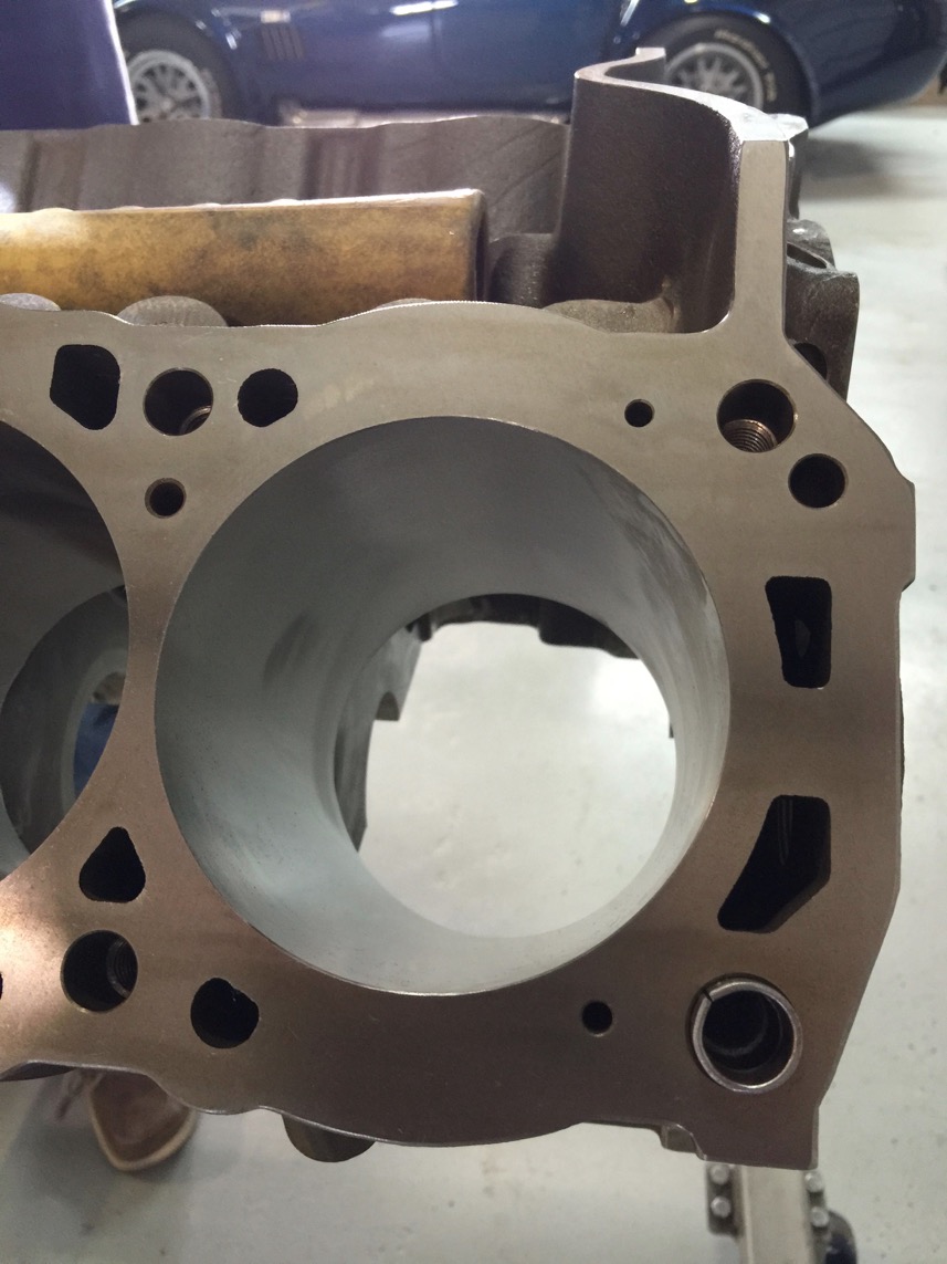
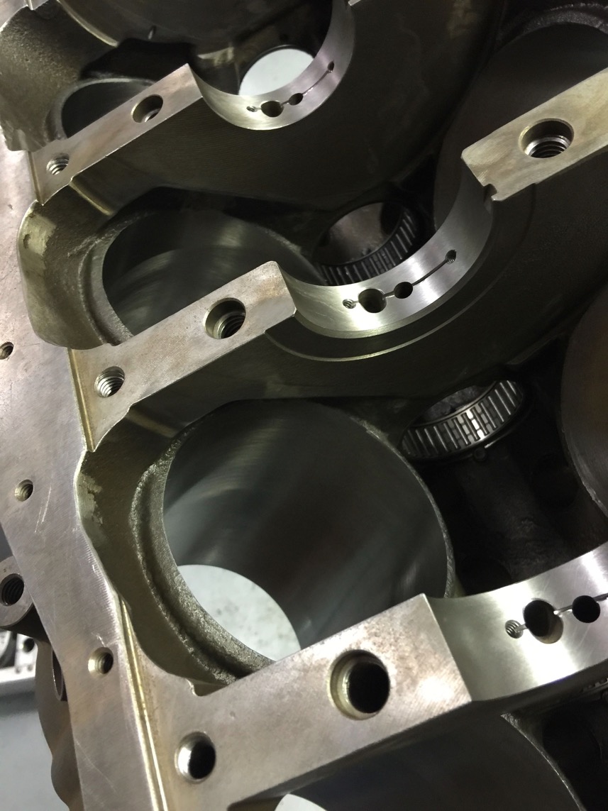
Main bearings drilled and cut for piston oil squirters (keep the pistons cool!) and a very fine cross hatching in the cylinder bores.
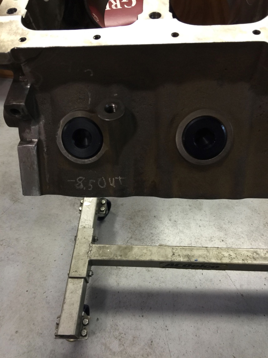
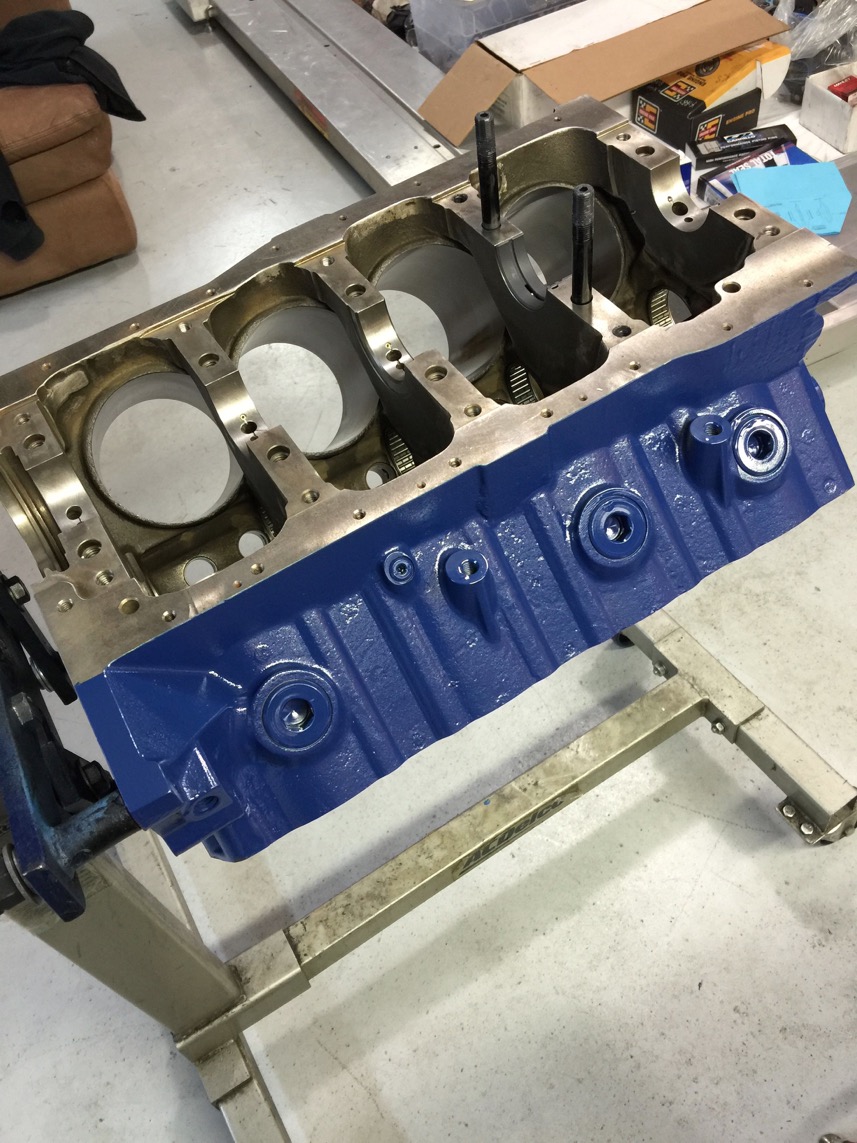
All painted and purty…. Those are freeze plugs with Orings, by the way.
Crankshaft and cam card
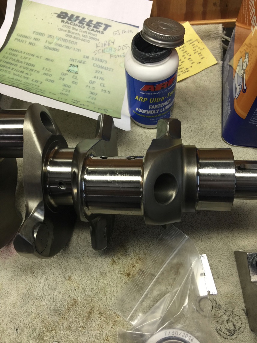

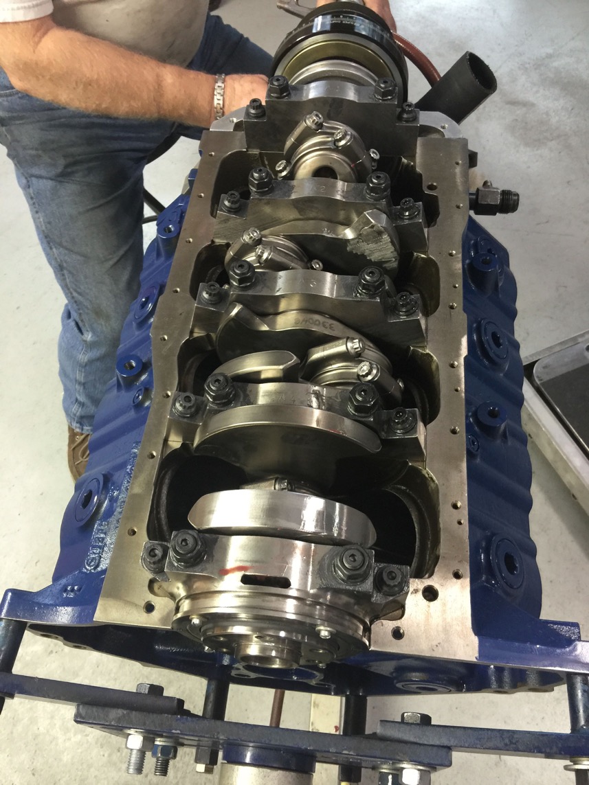
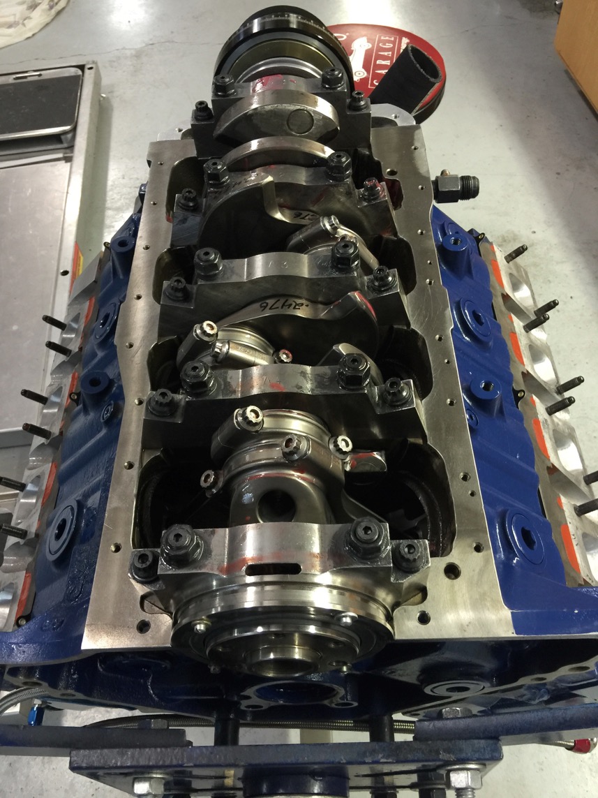
Crankshaft trial fitted for bearing clearance measurements.
All main bearings are .0025 to .0030 clearance based on traditional measurement means.
As an interesting comparison, the traditional micrometer measurements gave the above clearances.
We tried Plastigauge (both red and green) and each one says the clearances are slightly smaller at .002-.0025.
I found this interesting, because there seem to be two camps… Those that use Plastigauge and those that think it's crap!
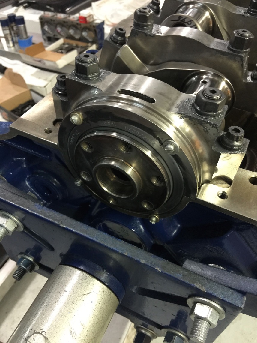
Modification with screws to hold the rear seal from moving.
Now then… ran into a problem.
Note the large chamfer of the ex-NASCAR crankshaft. The rod bearings won't fit side by side…
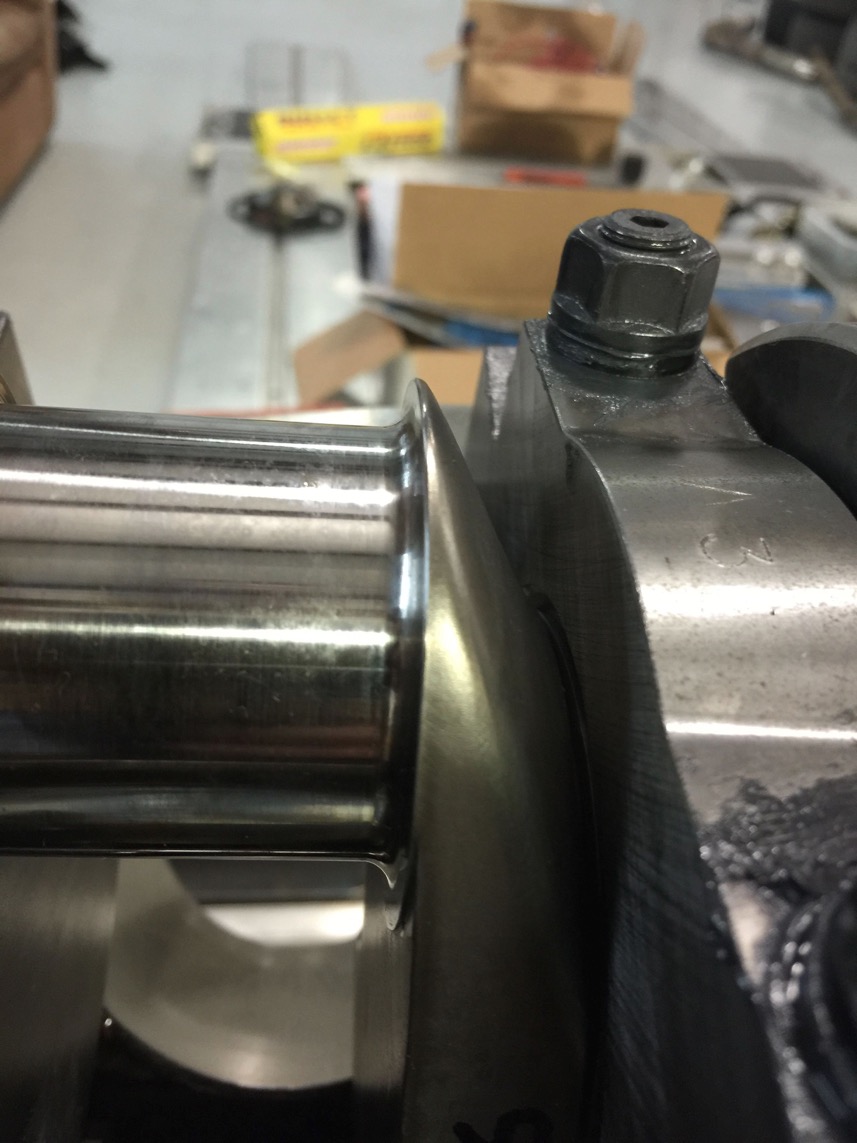
See how they don't fit the bevel on the rod?
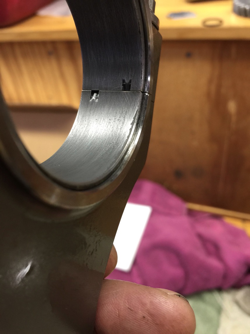
Here's how they were fixed…
A short movie…. to show how it was done.
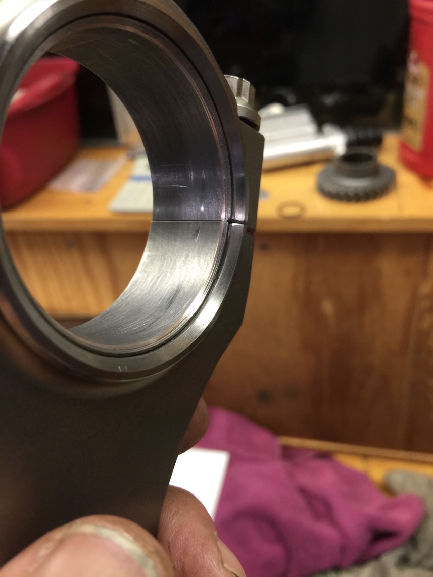
Result is shown below. Good to go!
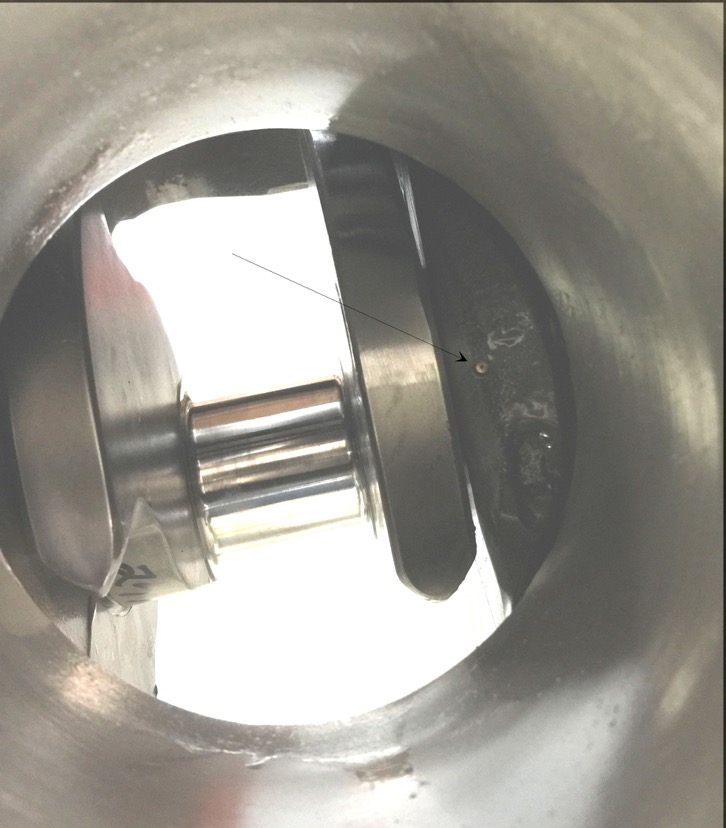
If you look REAL close, you can see the piston oil squirter to the right of the journal. I put an arrow….
They spray oil onto the underside of the piston for cooling.
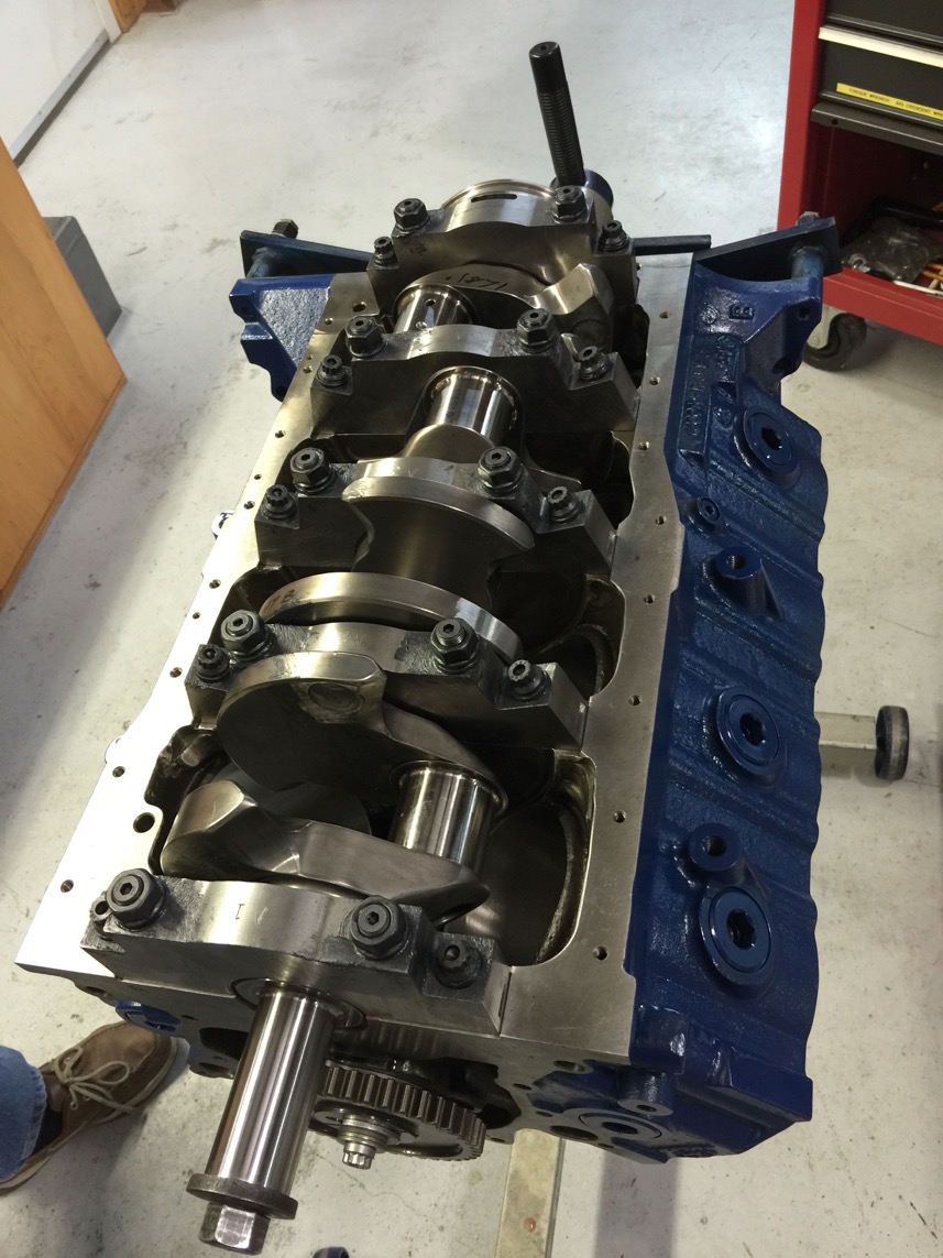
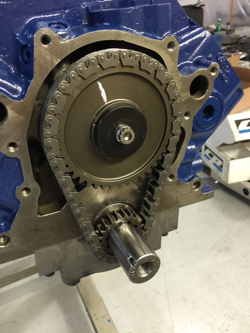
Timing chain installed after we degreed the cam to 1/2 a degree.
That’s an MP35N bolt holding it on there…
Also, the distributor gear had to be cut down slightly to clear the front camshaft bearing race.
Distributor fit has been checked and is good to go.
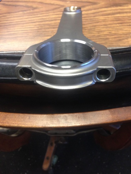
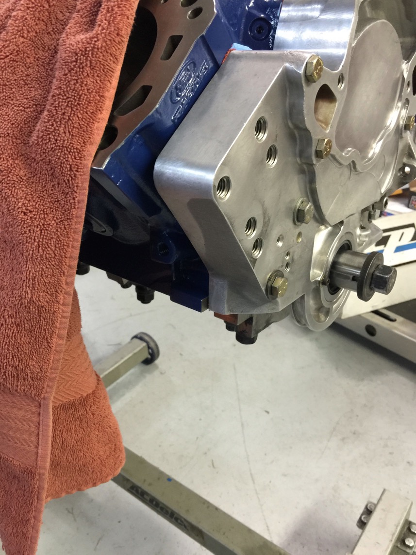
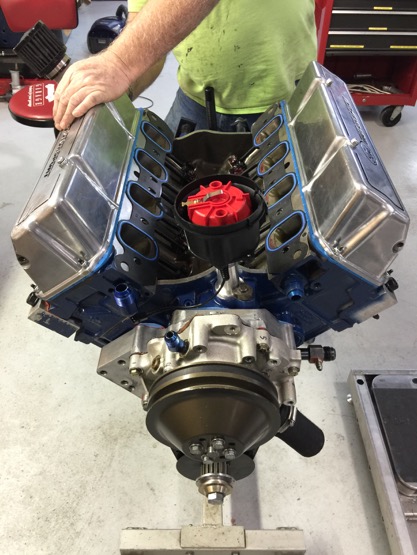
Nice ex-NASCAR front cover installed
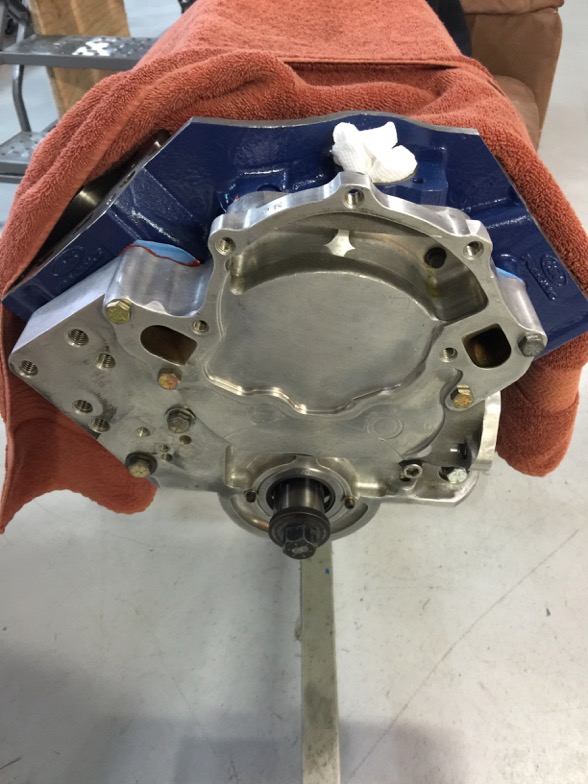
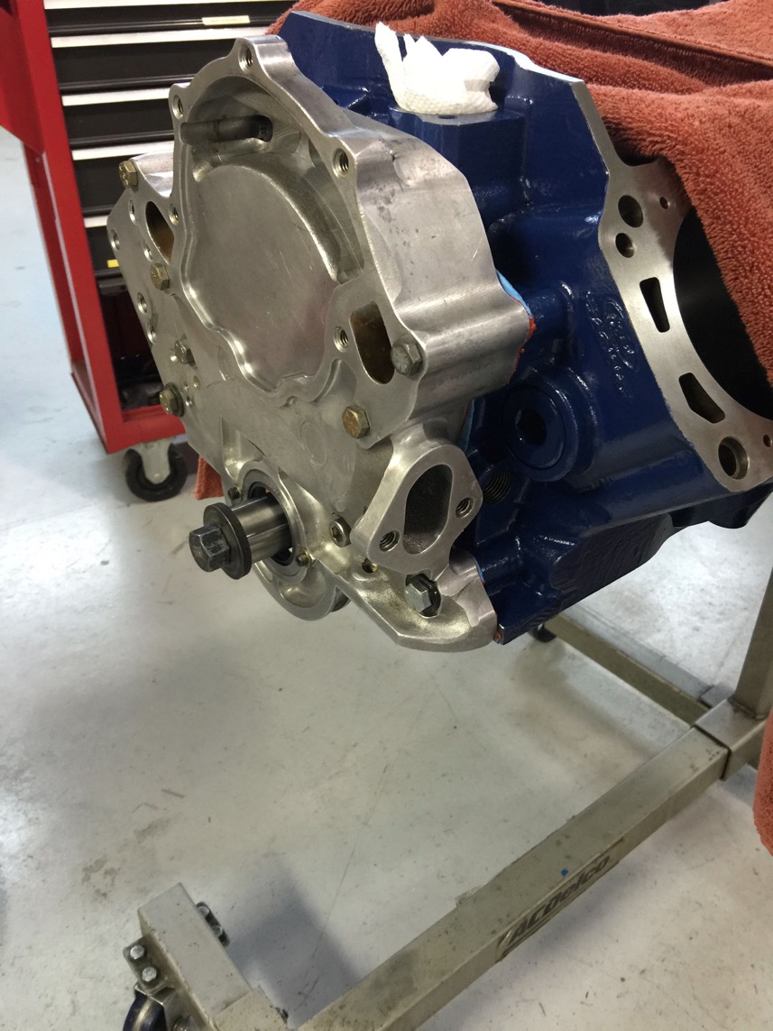
It is going to be an all new setup for the alternator and oil pump with this new cover.
Here are the CP pistons with Dyer rods all ready to go.
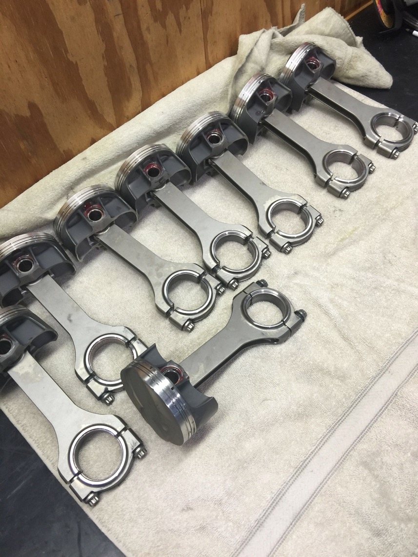
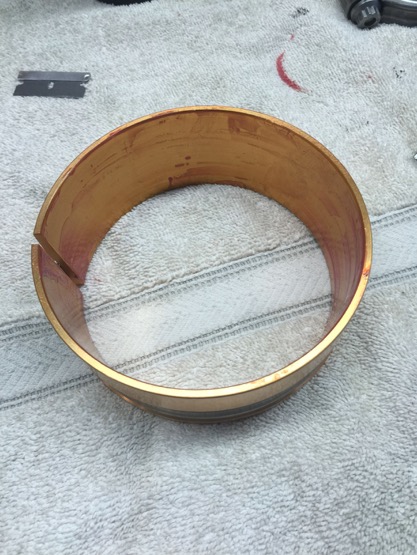
And this is a really nice ring compressor. Made the pistons go in really easy!
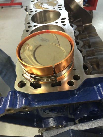
Here it is in action. Beats the hell out of everything I've ever used before…
Put the piston in and just give it a push.
Torquing the rod bolts with large feeler gauges to make sure there is no torque/twisting put on the rod bearings.
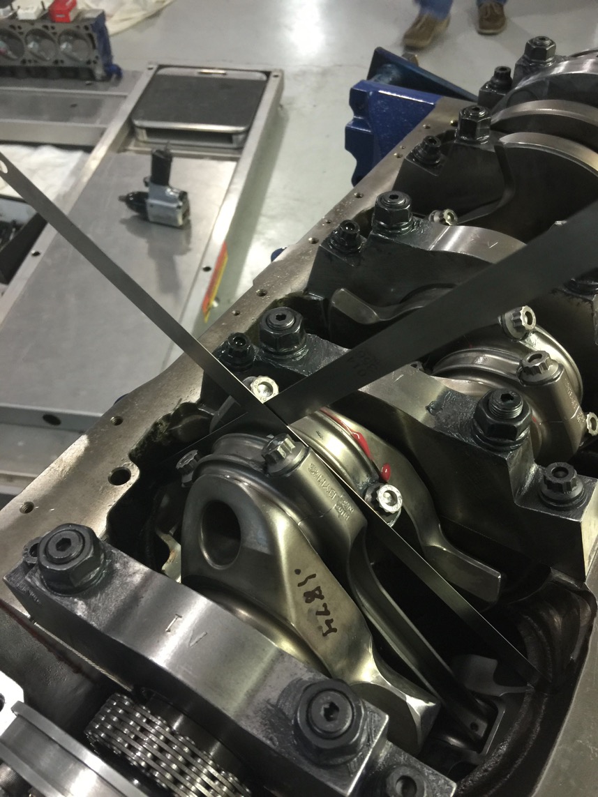
The bottom end all ready to go. Yes, Patricia, we quadrupled checked the rod bearing torques.
Checking piston to valve clearance.
By the way, we had issues with the port plates. The holes for the studs were not exactly spaced out right when the ends of the port plates were flush with the head. We had to take them off and redo them… Which meant reporting them… $$$$
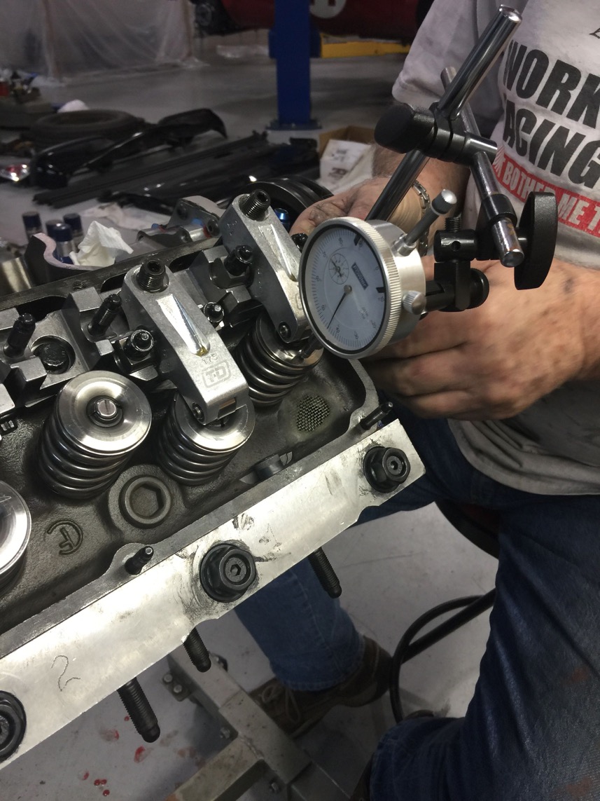
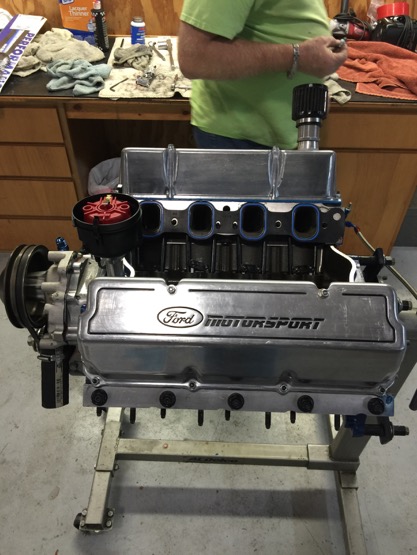
The heads are on, as you may have noticed.
Check out those very nice T&D rockers. One piece intake bracket and then you bolt the exhaust onto them.
No more welding!
The solid rollers are Jessel. Pushrods are Comp Cams.
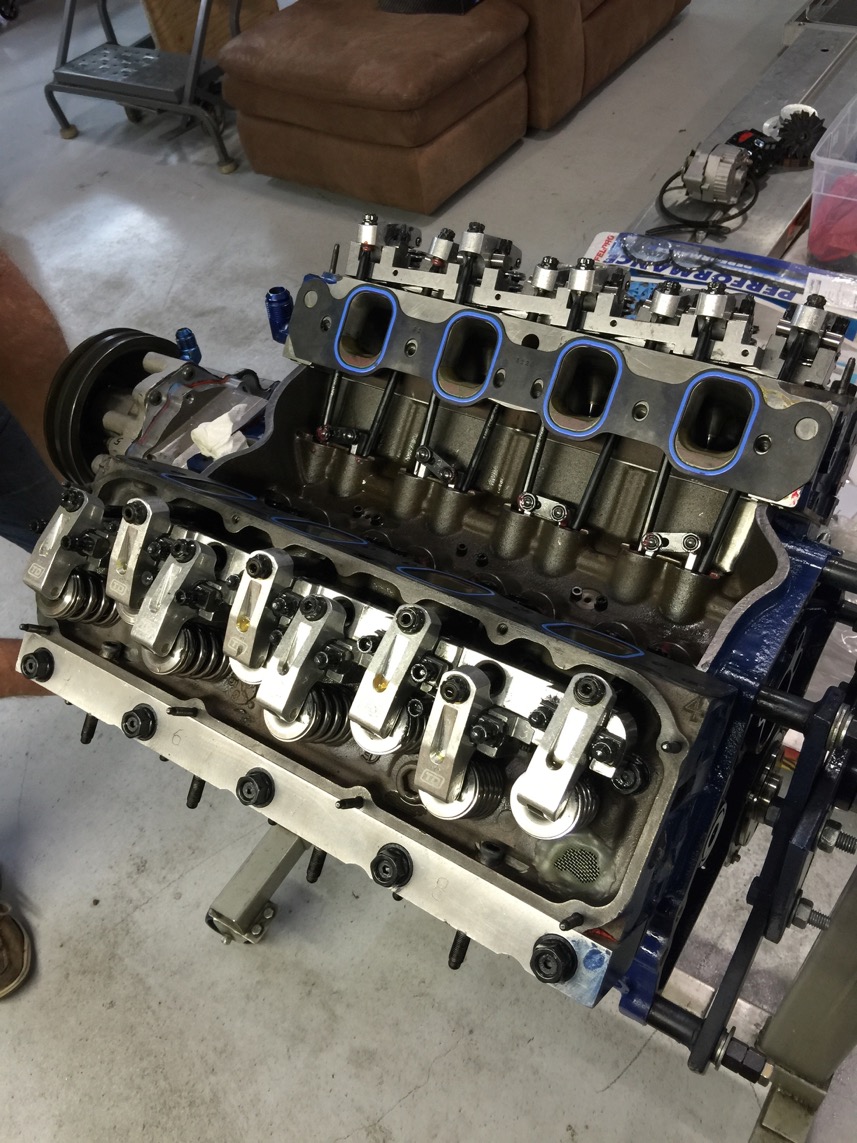
Distributor in and valve covers on. Later on, when the Webers went on, there wasn’t enough clearance and I had to get the smaller MSD distributor.
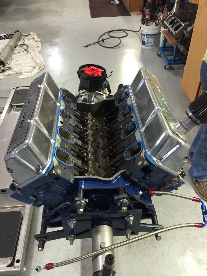
Sorta’ lookin’ like an engine, right?
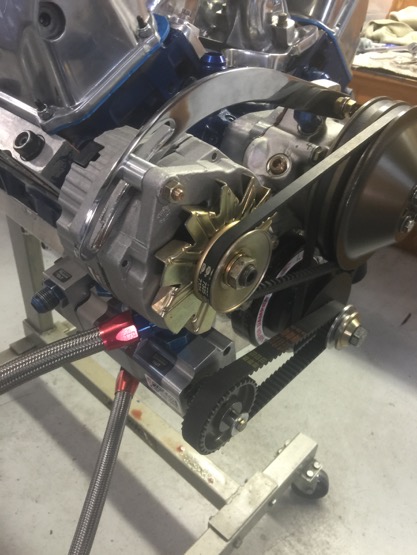
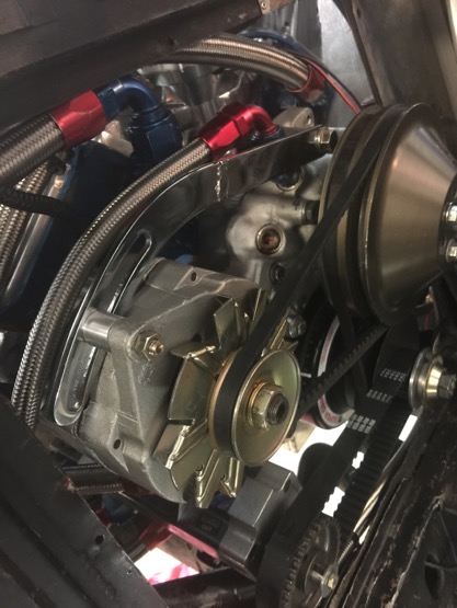
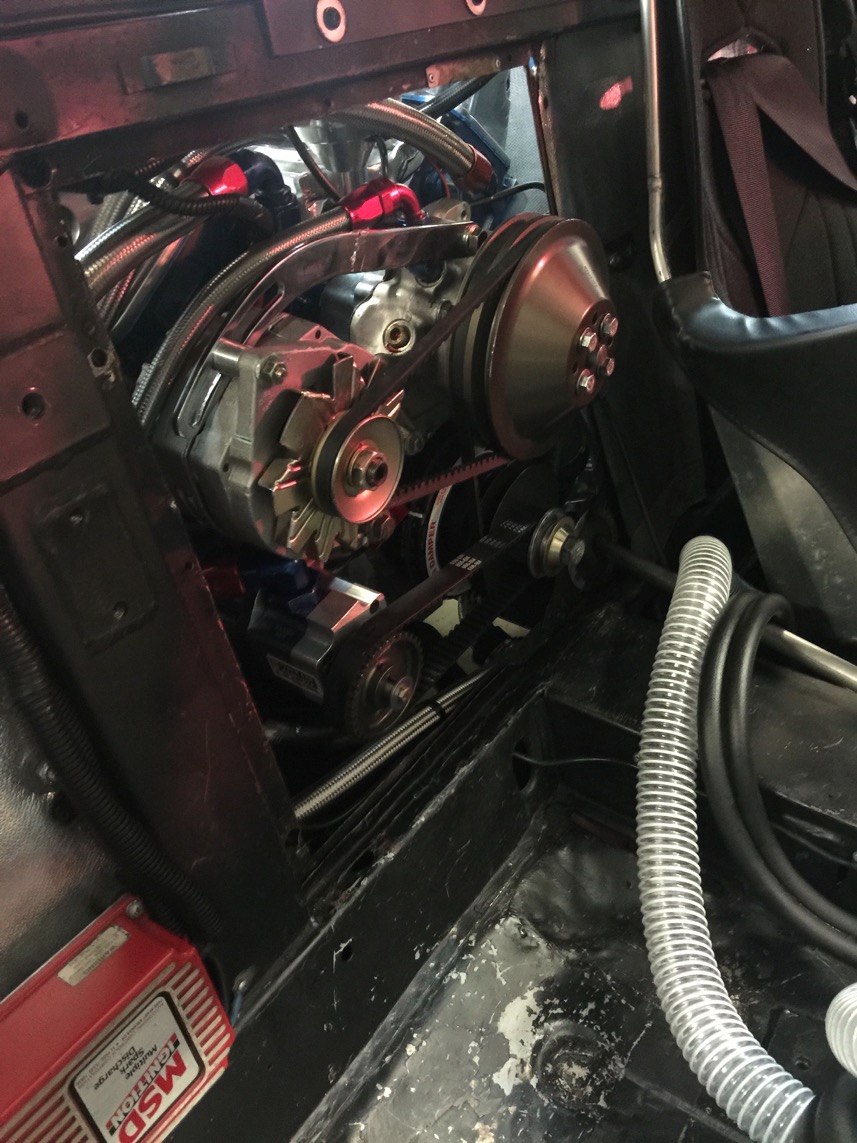
The alternator on, but I had to modify the bracket later as noted below. Wouldn’t go in the car since it was sticking out too far…
Now here’s where things got crappy… The oil pan is a dry sump aluminum.
It came off of a 9.5” SVO iron Windsor block.
It was installed on another iron Windsor SVO block (ask me about the story of the 20 second engine someday)
Do you think it would fit on THIS iron Windsor SVO block? Nope… I had to painstakingly modify almost every hole so we could bolt it on.
What a pain… But, it eventually fit.
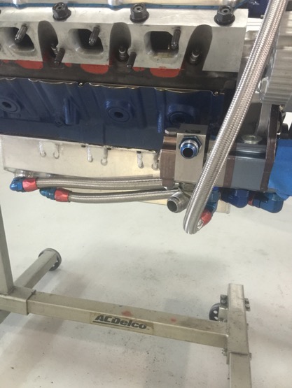
Pan on and oil lines being installed. Then hook them up to the pan.
That’s a three stage pump. Two for the sump and one for the lifter galley.
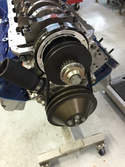
Balancer and water pump pulleys and belt installed. I had to modify the alternator tightener later on, too.
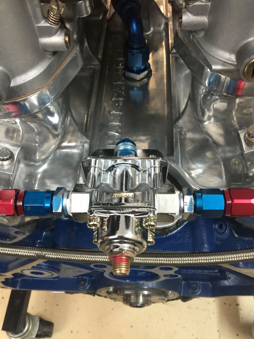
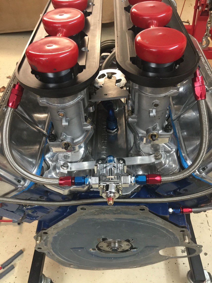
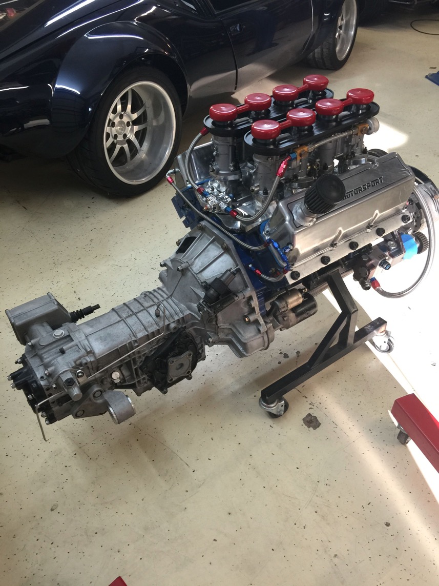
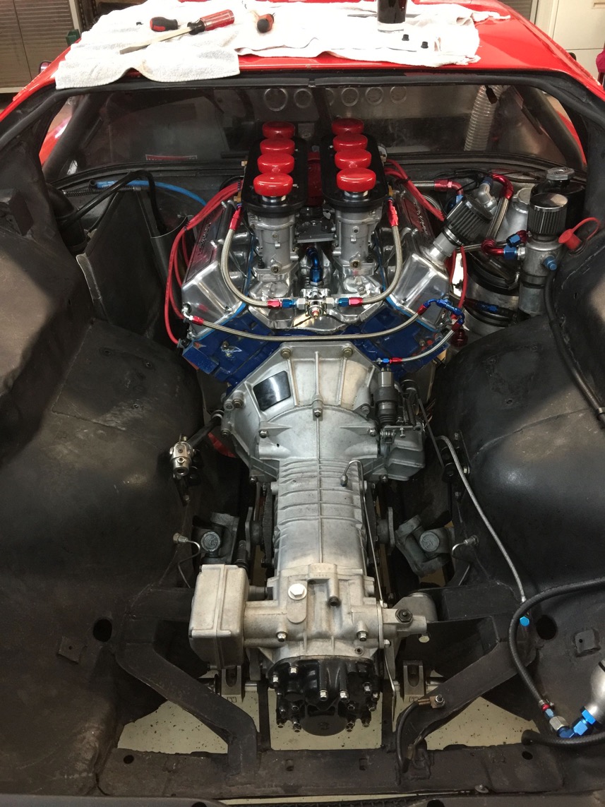
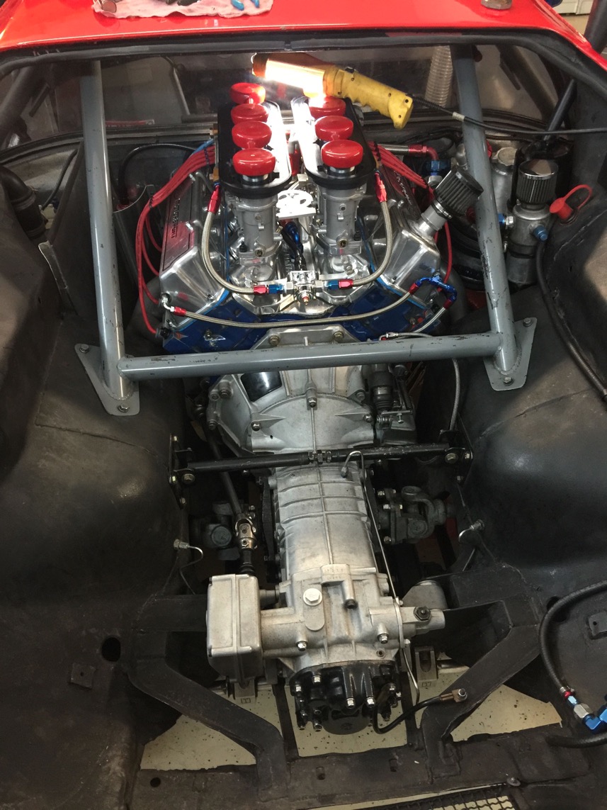
Webers are on (much to Tom and other’s disgust…) and fuel pressure regulator mounted. I tried three of those damned Holley regulators which EVERYBODY uses for Webers and are recommended for Webers. None of them would hold the fuel pressure steady.
I ended up using a different one from Mallory.
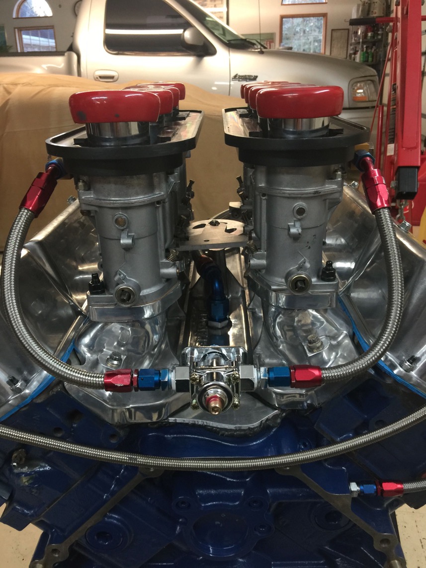
Close up of regulator and valley scavenge hose.
Yes, dear… We drilled a nice hole in the middle of a new Hall Pantera Weber manifold. Mr. Trusty probably groaned out loud…
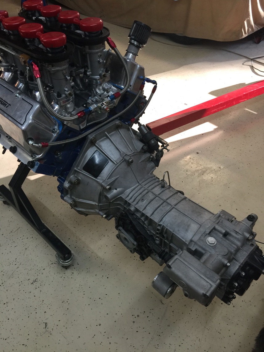
ZF is on. This went on the first time!
Just slid right in. NEVER had that happen before!
Tom and I attribute that to aligning the dowel pin holes. Tom has a special jig for that.
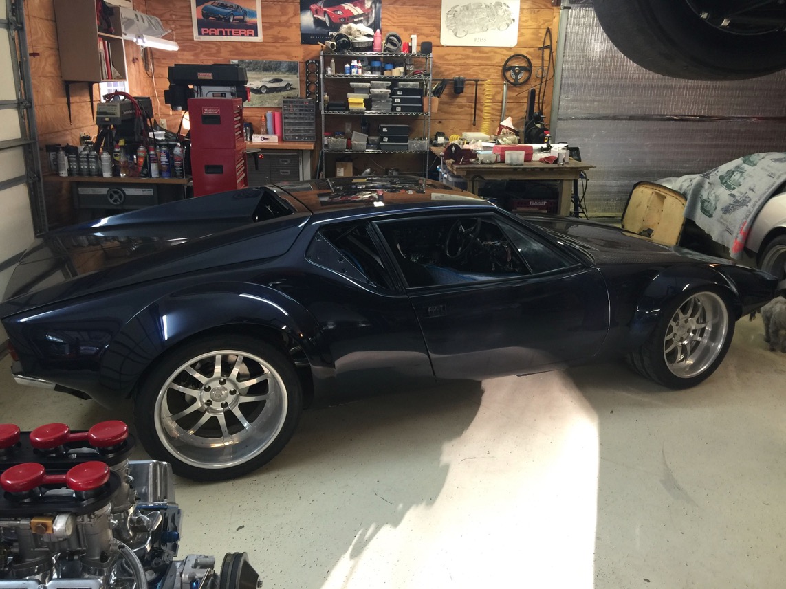
Yeah, I know…. there is a Pantera in the background… We worked on Dylan's car today, too.
Exhaust is on, but still needs some tweaks. His bumpers are on, too.
Now then… onto the wiring hookup.
Engine to go in soon. I need to index some plugs first, while it is easy.
OK, it's in the car.
Most everything hooked up. Note the AN4 oil lines to the valve covers for the valve spring oil spray.
Front, if you're interested, with the modified bracket.
Damned phone ran out of memory, but here's a real short movie of the first time to hit the switch.
Weber idle jets adjusted now. Third attempt seems pretty good. A short movie with it running.
And how about the sound of it hitting 8,000rpm on the front straight at TWS?
A big thanks to Tom Upton for all his assistance and mentoring. I have built engines before and they have held together, but I’ve never built one like this!